RoboRacer
Traditional training methods for solo track athletes have hit a plateau, with limited means to mimic real-race pacing and conditions. Athletes and coaches are in search of new, innovative solutions to break through these barriers and enhance performance. The RoboRacer aims to solve this problem by creating an autonomous robot that acts as a training partner for track athletes.
This robotic system uses advanced algorithms to follow lines on a track and adjust to various training regimens. With the integration of obstacle detection, it ensures safety for solitary training sessions. The accompanying app offers user-friendly control and access to essential training data, empowering athletes to refine their strategies and improve performance with actionable insights.
For instructions on how to use the RoboRacer, visit the usage documentation.
Table of Contents
Hardware
The RoboRacer was built from scratch using the following parts:
| Hardware | Description |
|---|---|
| Arrma Vortex Truck RC car | The RoboRacer was built with the base of an RC car as the body of the robot. |
| Arduino Portenta H7 Vision Bundle | This bundle includes our main microcontroller for the device and a camera system designed for vision processing. |
| Portenta Breakout Board | To simplify development. |
| HOOVO 3S Lipo Battery 10000 mAh | A battery to power the RoboRacer. |
| Power Distribution Board | A power distribution board is needed to power the robot and monitor its current. |
| ESP32 Development Board | WebUI hosting device. |
| Color Sensors | To detect the lines on the track. |
| Motion Sensor (IMU) | For detecting any type of motion values, such as acceleration and direction. |
| PETG Filament | Used for prototyping and 3D printing mounts onto the device. |
| MicroSD Modules | To store information on the device. |
| LiPo Battery Charger | Used to charge the LiPo batteries used for the RC car. |
| TCA9548A I2C Multiplexer | Differentiate color sensors, as multiple Devices share the same I2C address. |
| Hall Effect Sensor | To determine the speed of the RC car using rpm of the main axle. |
| PLA Filament White | Utilized for quicker prototyping, whilst the PETG will be used for final designs due to heat resistance. |
| OpenMV Cam H7 Plus | For line tracking. |
| Ultrasonic sensor: MB1260 XL-MaxSonar-EZL0 | For detecting obstacles in front of the robot. |
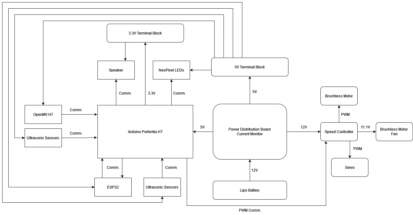
Electronics Diagram
This is the high-level electronic diagram:
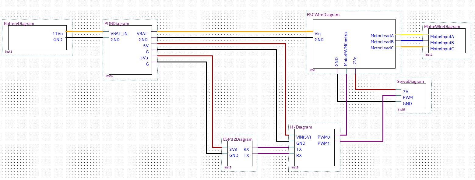
Wire Diagrams
Wire diagrams used during the development process:
RoboRacer Wire Diagram
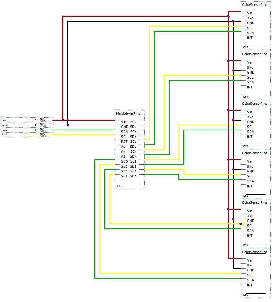
Color Sensor Wire Diagram
Obstacle Avoidance
Line tracking is implemented using the MB1260 XL-MaxSonar-EZL0
Components
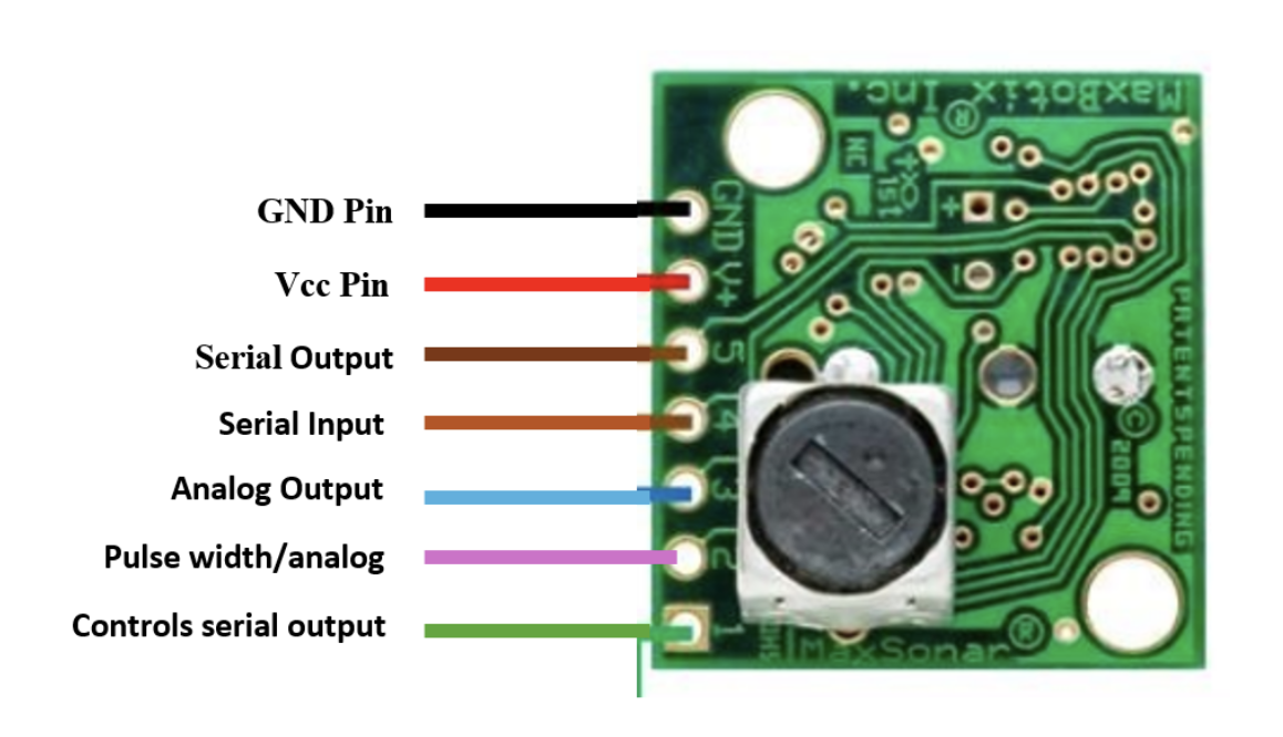
| Key Components | Description |
|---|---|
| Pin 1 (BW) | Controls serial output. |
| Pin 2 (PW/AN) | Outputs pulse width for range or analog voltage envelope. |
| Pin 3 (AN) | Outputs analog voltage representation of range. |
| Pin 4 (RX) | Controls ranging; high for continuous ranging, low to stop. |
| Pin 5 (TX) | Outputs serial data. |
| Pin 6 (+5V/Vcc) | Power supply input. |
| Pin 7 (GND) | Ground. |
Sensor Specifications
- Detection Range: 0 cm to 765 cm (up to 1068 cm for select models).
- Resolution: 1 cm.
- Power Requirements: 3.3V to 5.5V.
- Operation Frequency: 42 kHz.
System Implementation
- Sensor Placement: Mount the sensors at strategic locations to cover the required detection area.
- Data Processing: The microcontroller processes sensor data to determine the presence and distance of obstacles.
- Behavior Adjustment: Based on the sensor input, stops for advancement.
System Setup and Operation
The system setup involves connecting the MB1260 sensor to the microcontroller using the defined trigger and echo pins. During operation, the sensor continuously sends and receives ultrasonic pulses, with the microcontroller processing the serial data to determine the distance to obstacles.
For more detailed specifications, refer to the MB1260 datasheet
The Code
Initialization
We initialize the ultrasonic sensor and other necessary components:
UltrasonicSensor ultrasonicSensor(TRIG_PIN, ECHO_PIN);

void setup() {
    // Initialize Serial, UART, and other components
    ultrasonicSensor.init();
    myServo.attach(servoPin);
    myMotor.attach(motorPin);
}
Main Loop
The main loop continuously checks for obstacles and adjusts the robot’s movement:
void loop() {
    ultrasonicSensor.checkObstacle();
    if (stop) {
        myMotor.writeMicroseconds(1500); // Stop the motor
    } else {
        // Normal operations
        myServo.write(120);
        delay(2000);
        myServo.write(60);
        delay(2000);
    }
}
Obstacle Detection
The checkObstacle function in the UltrasonicSensor class checks the distance and stops the motor if an obstacle is detected:
void UltrasonicSensor::checkObstacle() {
    distance = getDistance();
    if (distance <= OBSTACLE_DISTANCE_THRESHOLD) {
        stop = true;
        myMotor.writeMicroseconds(1500); // Stop the motor
    } else {
        stop = false;
    }
}
Line Tracking
Line tracking is implemented using the OpenMV Cam H7 Plus
Components
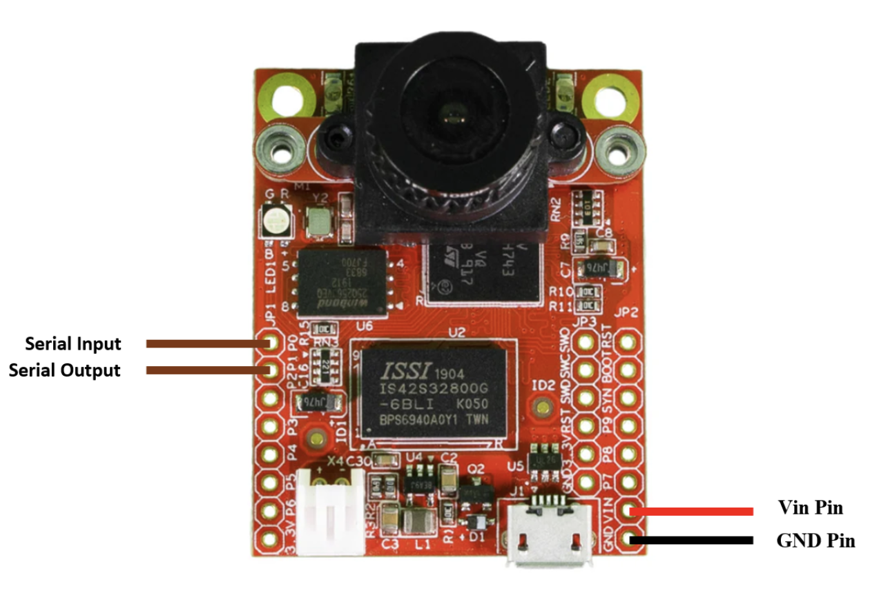
| Key Components | Description |
|---|---|
| P0 (RX) | Receiving data via UART |
| P1 (TX) | Transmitting data via UART |
| Vin | Power supply unit |
| GND | Ground |
Hardware Setup
- OpenMV Cam H7 Plus: To capture and process the image data.
- Arduino Board: To process data from the OpenMV Cam and control the motors.
- Motors and Motor Driver: To move the robot along the line.
Sensor Placement
- Place the OpenMV Cam H7 Plus at the front of the robot, angled slightly downward to capture the line.
- Ensure the camera is securely mounted and the field of view covers the line to be followed.
The Code
The line tracking algorithm with the OpenMV Cam H7 Plus involves capturing images, detecting lines within the image, calculating the error based on the line’s angle, and sending correction signals to the Arduino to adjust the robot’s direction.
- Capture Image: Continuously capture images using the OpenMV Cam.
- Detect Lines: Use image processing techniques to detect lines in the captured images.
- Calculate Error: Determine the deviation of the detected line from the desired orientation.
- Send Correction Signals: Transmit the error value to the Arduino via UART for motor adjustments.
Initialization
The camera is initialized with RGB565 pixel format for better line detection, and the frame size is set to QQVGA for faster processing. UART communication is established to send data to the Arduino. Additionally, the target angle for the line is set to 90 degrees, and a threshold is defined for allowable error.
import sensor
import image
import time
import pyb

ENABLE_LENS_CORR = False  # Turn on for straighter lines...

sensor.reset()
sensor.set_pixformat(sensor.RGB565)  # RGB565 format for better line detection
sensor.set_framesize(sensor.QQVGA)
sensor.skip_frames(time=2000)
clock = time.clock()

target_theta = 90  # Assuming we want the line to be vertical
some_threshold = 20

# Initialize UART
uart = pyb.UART(3, 115200)
Main Loop
The main loop captures an image and optionally corrects for lens distortion. It then detects lines in the image, selects the strongest line based on the rho value, and calculates the angular error relative to the target angle. Depending on whether the error is within the defined threshold, the line is drawn in green or red. Finally, the error value is sent to the Arduino via UART, and the FPS is printed for debugging purposes.
while True:
    clock.tick()
    img = sensor.snapshot()
    if ENABLE_LENS_CORR:
        img.lens_corr(1.8)  # Correction for lens distortion

    lines = img.find_lines(threshold=1000, theta_margin=25, rho_margin=25)
    if lines:
        # Sort lines based on the magnitude of the rho value
        lines.sort(key=lambda x: abs(x.rho()))
        strongest_line = lines[0]  # Select the strongest line

        detected_theta = strongest_line.theta()
        error = detected_theta - target_theta  # Calculate the angular error
        if abs(error) < some_threshold:
            img.draw_line(strongest_line.line(), color=(0, 255, 0))
            print("Angle: %d, Error: %d" % (detected_theta, error))
        else:
            img.draw_line(strongest_line.line(), color=(255, 0, 0))
            print("Angle: %d, Error: %d - OUT OF BOUNDS" % (detected_theta, error))

        # Send the error value to Arduino
        uart.write("%d\n" % error)
    print("FPS %f" % clock.fps())
Compilation and Upload
- OpenMV IDE:
- Open the OpenMV IDE.
- Connect your OpenMV Cam H7 Plus to your computer.
- Copy the code into the script editor.
- Save the script to the OpenMV Cam.
- Arduino:
- Use the Arduino IDE to write a corresponding script to receive the error value via UART and adjust motor speeds accordingly.
- Upload the script to the Arduino board.
For more detailed specifications, refer to the OpenMV Cam H7 Plus Datasheet
Speed Control
Speed control is implemented using a NJK-5002C Hall Effect Sensor
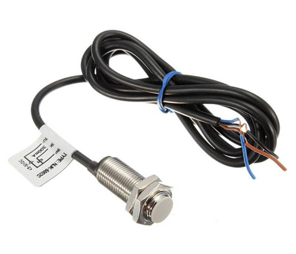
| Key Components | Description |
|---|---|
| GPIO 5 | Used to receive data from the sensor |
| Vin | Power supply input.(5V) |
| GND | Ground |
Sensor Placement
- Place the hall effect sensor close to the main axel of the robot.
- Add a small magnet in line with the hall effect sensor on the axel.
- Adjust how close the sensor is to the axel so it only detects the magnet when it’s close. (the sensor should have a red led on the back when it detects the magnet)
The Code
Initialization
The hall effect sensor is initialized by setting its pin to an input.
pinMode(hallPin, INPUT);
Then to get data for the speed we have to initialize two interrupts, one that counts a rotation for the hall effect sensor and one that calculates the speed every half a second.
attachInterrupt(hallPin, count_rotation, FALLING);  //attaching the interrupt
// execute getRPS every 500ms
if (ITimer0.attachInterruptInterval(500000, get_speed))
{
  Serial.print(F("Starting ITimer0 OK"));
}
else{
  Serial.println(F("Failed to start ITimer0"));
}
Runtime Code
During runtime the code utilizes the get speed interrupt function to update the motors speed based on it’s current speed and target speed.
void get_speed(){
 rps = rotations*2;
 speedMPS = rps*metersPerRotation;
 rotations = 0;


 //changes the target PWM based on the new speed
 if (speedMPS > targetSpeed && targetPWM > 1550)
 {
   targetPWM --;
 }
 else if (speedMPS < targetSpeed && targetPWM < 2000){
   targetPWM ++;
 }
}
void count_rotation() {
   rotations ++;
}
User Communication
Installation
Using PlatformIO
PlatformIO - “PlatformIO is a cross-platform, cross-architecture, multiple framework, professional tool for embedded systems engineers and for software developers who write applications for embedded products.”
- Install PlatformIO IDE
- Copy esp32-s3-devkitm-1.json from the public directory in this project and paste it into the .platformio/platforms/espressif32/boards folder on your personal system.
- In the web-ui directory, run the npm install command
- Follow Compilation steps below to compile and run this project
NPM
The modules used for the front end web application are npm modules, which can be installed by running npm install --legacy-peer-deps while in the web-ui/ directory.
Note: –legacy-peer-deps is necessary due to conflicting versions of the node modules.
The Project
ESP32-S3-DevkitM-1
Components
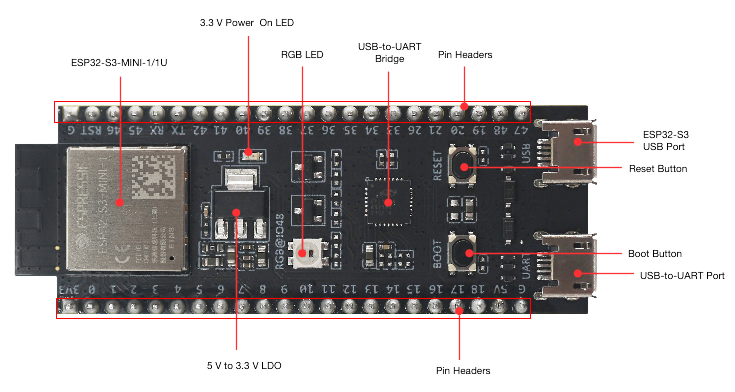
Figure 1. ESP32 DevkitM-1 Components
| Key Component | Description |
|---|---|
| ESP32-S3-MINI-1/1U | ESP32-S3-MINI-1 and ESP32-S3-MINI-1U are two general-purpose Wi-Fi and Bluetooth Low Energy combo modules that have a rich set of peripherals. ESP32-S3-MINI-1 comes with a PCB antenna. ESP32-S3-MINI-1U comes with an external antenna connector. At the core of the modules is ESP32-S3FN8, a chip equipped with an 8 MB flash. Since flash is packaged in the chip, rather than integrated into the module, ESP32-S3-MINI-1/1U has a smaller package size. |
| 5V to 3.3V LDO | Power regulator that converts a 5 V supply into a 3.3 V output. |
| Pin Headers | All available GPIO pins (except for the SPI bus for flash) are broken out to the pin headers on the board for easy interfacing and programming. For details, please see Header Block. |
| USB-to-UART Port | A Micro-USB port used for power supply to the board, for flashing applications to the chip, as well as for communication with the chip via the on-board USB-to-UART bridge. |
| Boot Button | Download button. Holding down Boot and then pressing Reset initiates Firmware Download mode for downloading firmware through the serial port. |
| Reset Button | Press this button to restart ESP32-S3. |
| ESP32-S3 USB Port | ESP32-S3 full-speed USB OTG interface, compliant with the USB 1.1 specification. The interface is used for power supply to the board, for flashing applications to the chip, for communication with the chip using USB 1.1 protocols, as well as for JTAG debugging. |
| USB-to-UART Bridge | Single USB-to-UART bridge chip provides transfer rates up to 3 Mbps. |
| RGB LED | Addressable RGB LED, driven by GPIO48. |
| 3.3 V Power On LED | Turns on when the USB power is connected to the board. |
Memory Space Allocation via Partitioning
Generally, the ESP32 should have the default partitioning scheme for 8MB, but due to the size needed to be allocated for the filesystem image, a new partitioning set, partitions_custom.csv, has been created. As can be seen below, we reallocated memory from app1 to also be included in the spiffs section.
#default_8MB.csv
# Name,   Type, SubType, Offset,  Size, Flags
nvs,      data, nvs,     0x9000,  0x5000,
otadata,  data, ota,     0xe000,  0x2000,
app0,     app,  ota_0,   0x10000, 0x330000,
app1,     app,  ota_1,   0x340000,0x330000,
spiffs,   data, spiffs,  0x670000,0x180000,
coredump, data, coredump,0x7F0000,0x10000,

#partitions_custom.csv
# Name,   Type, SubType, Offset,  Size, Flags
nvs,      data, nvs,     0x9000,  0x5000,
otadata,  data, ota,     0xe000,  0x2000,
app0,     app,  ota_0,   0x10000, 0x330000,
spiffs,   data, spiffs,  0x340000,0x4B0000,
coredump, data, coredump,0x7F0000,0x10000,
The Code
Web Server Code
The ESP32 is treated as an asynchronous web server, responding to a connected users HTTP requests as it recieves them. It holds the primary job of communication between the user and the RoboRacer, utilizing its UART (Universal asynchronous receiver-transmitter) capabilities to recieve and transmit data to the Portenta H7. This section will serve as a breakdown of how the code in main.cpp accomplishes this task.
if (!SPIFFS.begin(FORMAT_SPIFFS_IF_FAILED))
{
    Serial.println("An Error has occurred while mounting SPIFFS");
    return;
}
First we set up our SPIFFS (Serial Peripheral Interface Flash File System), which will allow us to format our files as listed in the ./data directory. SPIFFS can now act as a filesystem, which we use in the following code.
server.serveStatic("/", SPIFFS, "/").setDefaultFile("index.html");
This sets our server (which was set up on port 80) to serve our web app when connected to. The ESP32 WiFi is set up as an Access Point, which means we are simply allowing devices to connect with us, but not providing actual WiFi.
WiFi.softAP(ssid, password, 1, 0, 1);

IPAddress IP = WiFi.softAPIP();
This code sets up the Access Point with ssid (wifi name) “ESP32-Access-Point”, password “123456789”, and several other options, notably limiting the maximum number of connections to 1, so no others can connect when the user is connected. The IP Address is 192.168.4.1, which we will the user on the side of the RoboRacer in it’s final implementation.
server.onRequestBody([](AsyncWebServerRequest *request, uint8_t *data, size_t len, size_t index, size_t total) {
      if (request->method() == HTTP_POST) {
         if (!handlepostData(request, data)) {
            Serial.print("Something went wrong!!!");
            request->send(400, "text/plain", "false");
         }
         request->send(200, "text/plain", "true");
      }
      if (request->method() == HTTP_GET) {
        //...
      }
      //...
    });
The above code details how we respond to HTTP requests. When we receive a request, we check what method it is, then we handle that request with built in functionality that decodes the body of the request and checks what it contains, like so:
    JsonDocument jsonDoc;
    DeserializationError error = deserializeJson(jsonDoc, (const char *)datas);
    //...
    if (jsonDoc.containsKey("name")){
        String _name = jsonDoc["name"].as<String>();
        Serial.println(_name);
    }
    //...
To communicate directly to the user, we utilize websockets, which allow us to send messages to our WebSocket, ws, by using ws.textAll(), which sends a message to our polling websocket element on the web application. We are also able to tell when the user connects and disconnects from the application using websockets via built in event headers WS_EVT_CONNECT and WS_EVT_DISCONNECT.
AsyncWebSocket ws("/ws");

void notifyClients(String message) {
  ws.textAll(message);
}

void onEvent(AsyncWebSocket *server, AsyncWebSocketClient *client, AwsEventType type, void *arg, uint8_t *data, size_t len) {
  switch (type) {
    case WS_EVT_CONNECT:
      Serial.printf("WebSocket client #%u connected from %s\n", client->id(), client->remoteIP().toString().c_str());
      break;
    case WS_EVT_DISCONNECT:
      Serial.printf("WebSocket client #%u disconnected\n", client->id());
      break;
    case WS_EVT_DATA:
      handleWebSocketMessage(arg, data, len);
      break;
    case WS_EVT_PONG:
    case WS_EVT_ERROR:
      break;
  }
}

void initWebSocket() {
  ws.onEvent(onEvent);
  server.addHandler(&ws);
}
Web Application Code
The front end of the web application is written in React JS. Leveraging components, there are many included in src/components:
Controls: The controls component is simply a container for its child components, SpeedProfiles and StartStopButton
<div className='controls-container'>
    <h1>Controls</h1>

    <SpeedProfiles className='inputs-container' />
    <StartStopButton className='start-stop-container' />]
</div>
SpeedProfiles: The speed profiles component handles the user’s inputs and directly communicates with the ESP32 so that it can set the desired speed.
When the user clicks the ‘set’ button on the page, a POST request is sent to the ESP32:
function handleClick() {
    const data = {
        time: time,
        distance: distance
    }

    console.log('submit inputs:', data);

    fetch('/postData', {
        method: 'POST',
        body: JSON.stringify(data)
    })
}
Similarly, when a user chooses to save the speed profile for future use, a POST request is sent:
function handleSave() {
    alert('Functionality not yet implemented!')

    const data = {
        name: name,
        time: time,
        distance: distance
    }

    fetch('/addSpeedProfile', {
        method: 'POST',
        body: JSON.stringify(data)
    })
}
These speed profiles are saved and loaded from a JSON file, populated into objects:
function useSpeedProfiles() {
    return useMemo(() => {
        return Object.keys(speedProfilesData).map((profileName) => ({
            value: profileName,
            label: profileName,
        }));
    }, []);
}
Note: this feature is not yet implemented (see Next Steps)
StartStopButton: The start and stop buttons also send requests to the ESP32 using POST requests:
function handleStart() {
    console.log("Start RoboRacer");

    const data = {
        directive: 'start'
    }

    fetch('/start', {
        method: 'POST',
        body: JSON.stringify(data)
    })
}

function handleStop() {
    console.log("Stop RoboRacer");

    const data = {
        directive: 'stop'
    }

    fetch('/stop', {
        method: 'POST',
        body: JSON.stringify(data)
    })
}
Performance: The performance component displays the data gathered from the RoboRacer during a run using a GET request:
// yet to be implemented
Libraries Used
- WiFi.h
- Allows us to set up the ESP32 as an access point and connect to another device via WiFi
- ESPAsyncWebServer.h
- Treats the ESP32 as an asynchronous web server, allowing us to process HTTP Requests from the user
- SPIFFS.h
- Lets us work with the spiffs section of our board, storing a filesystem in the flash memory
- FS.h
- Makes a more cohesive filesystem on the ESP32, letting us navigate through it as one would a computer
- ArduinoJson.h
- Lets us both create and parse through JSON objects, allowing sending and retrieving of data from user
- React Router DOM
- Builds user interface to route to pages
- React Joystick Component
- Allows usage of joystick on a dev page, to direct RoboRacer
- Material UI
- Styled components to add to the code, to make the CSS simpler
- Dayjs
- To allow for receiving time inputs
Compilation
- In the web-ui directory, run the nmp run build command. This will compile the web application and move the appropriate files out of the /static directory.
- Delete the contents of the ./data directory
- Copy the contents of ./web-ui/build and paste them to ./data
- In the index.html file, search for the “static” keyword using ctrl+f. Update both instances of the word to reflect the new file structure, as demonstrated below (why are we doing this?):
<script defer="defer" src="/static/js/main.72aff11b.js"> --> <script defer="defer" src="/js/main.72aff11b.js">

<link href="/static/css/main.cf5403a1.css" rel="stylesheet"> --> <link href="/css/main.cf5403a1.css" rel="stylesheet">
- Connect the ESP32 to your computer via it’s USB Port
- Run the platformio “Build”, “Upload”, “Build Filesystem Image”, and “Upload Filesystem Image” commands (which can be found in the PlatformIO portion of VSCode’s extention bar, or by using PlatformIO’s commands in the terminal)
- You are now ready to connect your device to the ESP32’s WIFI Access Point!
Extra Notes
Why Are We Deleting Static?
We delete the /static directory and update index.html to no longer include it because spiffs can only store files up to 32 bytes long. data\static\js\main.72aff11b.js.map is 35 bytes long, and thus we remove the static directory from the name to reduce it to 28 bytes.
Sources
Esspressif ESP32-S3-DevkitM-1 User Guide
Next Steps
Given the time constraints of this project, many functionalities were not implemented and some could be improved upon.
Features to Add
- Follow-Me Mode: in this mode, the RoboRacer will autonomously follow the runner while maintaing a parallel distance
- RoboRacer follows lines and intersecting lines on a track
- Real-time metrics displayed on the interface: battery life, performance metrics (especially as the race is going)
- Save speed profiles to ESP32
Improvements
- Grey-out start button on web UI until the robot is ready to go
- Extract JSON data files to live on ESP32 instead of in the React website code